E-Reg

E-Reg integrated with fluids system
Overview:
Over the course of the 2025-2026 school year, I developed a custom electromechanical pressure regulator valve (E-Reg) to control ullage pressure in our liquid oxygen tank for our LOX feed system. This regulator replaced the dome-loaded regulator we previously used for tank pressurization.
Core requirement: maintain tank pressure to within ± 10 psi of the setpoint pressure throughout the entire duration of cold flow and static fire tests.
The E-Reg is a modified high-pressure ball valve actuated by a servo that serves as a pressure regulator for our LOX tank. Our rocket’s architecture is a pressure-regulated hybrid, which requires our LOX tank ullage to be consistently pressurized (450 psi target) during an engine fire, feeding LOX through our injector. The E-Reg achieves this via an active control loop; a PID controller with gain scheduling adjusts the valve angle based on pressure transducer readings from our LOX tank and COPV. I was the responsible engineer on this project; I owned the design and analysis of the valve, the control architecture, integration with the fluids system, and testing of this component. The design and creation of the board that took pressure readings, ran the control loop, and sent signals to the servo were owned by the electronics team. The C++ code running the E-Reg was co-written by electronics team leads and me. The E-Reg successfully held tank pressure to within ± 10 psi at the final static fire of 2026.

Milled down I-port from first attempt


I-port insert:
The ball valve is modified with an I-shaped insert (I-port) that helps make the rate of area increase constant. This constant valve gain gives greater control authority to the PID and ensures it can remain stable throughout the entire operating regime. Without it, we might’ve had to implement different gain sets at different angle ranges to account for the constant changes in dA/dθ that come with a circular bore.
When starting this project, I considered two key alternative valve architectures before settling on this servo-actuated I-port ball valve. I first considered using solenoid valves with a bang-bang (on/off) control scheme. This architecture would have been much simpler to implement, as it would have been a COTS solenoid valve with a simple on/off control loop, potentially with a deadband as well. The downside of a control loop like this is that the process variable will consistently oscillate around the setpoint rather than converging to the setpoint. We also found it difficult to source a high-pressure solenoid valve with a high enough Cv to keep a 29 L tank pressurized with 23 L of LOX draining over a target 12-second burn time. We also considered purchasing a V-port ball valve, whose bore resembles a triangle rather than a circle, giving us equal-percentage flow characteristics. Again, we ran into difficulties sourcing a high-pressure V-port ball valve. Ultimately, I decided to pursue a custom port insert held in place with an interference fit.
I sized the insert to achieve a .0013” diametric interference with the ball valve bore, holding the insert in place with a calculated pressure of 2993 psi, giving an FOS of 1.88 for axial retention against our COPV MEOP of 4500 psi. The insert was machined out of 303 stainless steel on a Haas ST-20Y. I designed and machined a 6061 aluminum jig to align the port and the ball during installation. In our first try, my teammates and I heated the ball in an oven and attempted to install the I-port. Due to alignment errors, we failed on the first try and achieved a partial installation. Using custom soft jaws, we milled down the portion of the insert that was sticking out and used that ball only for compressed air testing. In our second try, we heated a new ball up with a blowtorch instead of using an oven; I calculated that the bore of the ball valve would expand by ~.003” at 350 ℃, giving us roughly .002” of clearance to get the insert in before the ball cooled. We were successful in our second attempt.
Machining the insert
Physical design:
I decided to use an AGFRC A280BVSW servo to actuate the ball valve. With 110 kg*cm hold torque and 60 degrees of travel in .09s, this servo was a great candidate for fast actuations of a high-pressure ball valve. I designed a coupler to connect the servo arm to the ball valve stem. I created CAM toolpaths and machined this coupler on the Haas Mini Mill. I first made an aluminum version of this coupler. During testing, we found that the high-torque rotation of the servo caused the ball valve stem to dig into the coupler, worsening the backlash of the system over time. Additionally, due to space constraints in our vehicle’s fluid system, I had to redesign a shorter version of the coupler and mill the servo arm down as well. I machined this second iteration coupler out of 303 stainless steel.

Aluminum coupler (right), 303 Stainless Steel coupler (center)
The servo mount was designed by my teammate and SLS-printed out of Nylon. Its thin profile aids in integration in our space-restricted fluids stack. Additionally, the cutout next to the ball valve allows us to remove the servo and mount while keeping the ball valve in place. Removing the ball valve requires the removal of our fitting adapter and lots of tubing, which is incredibly time-consuming. This one design choice saved hours of work every time the servo or mount had to be removed and reinstalled.
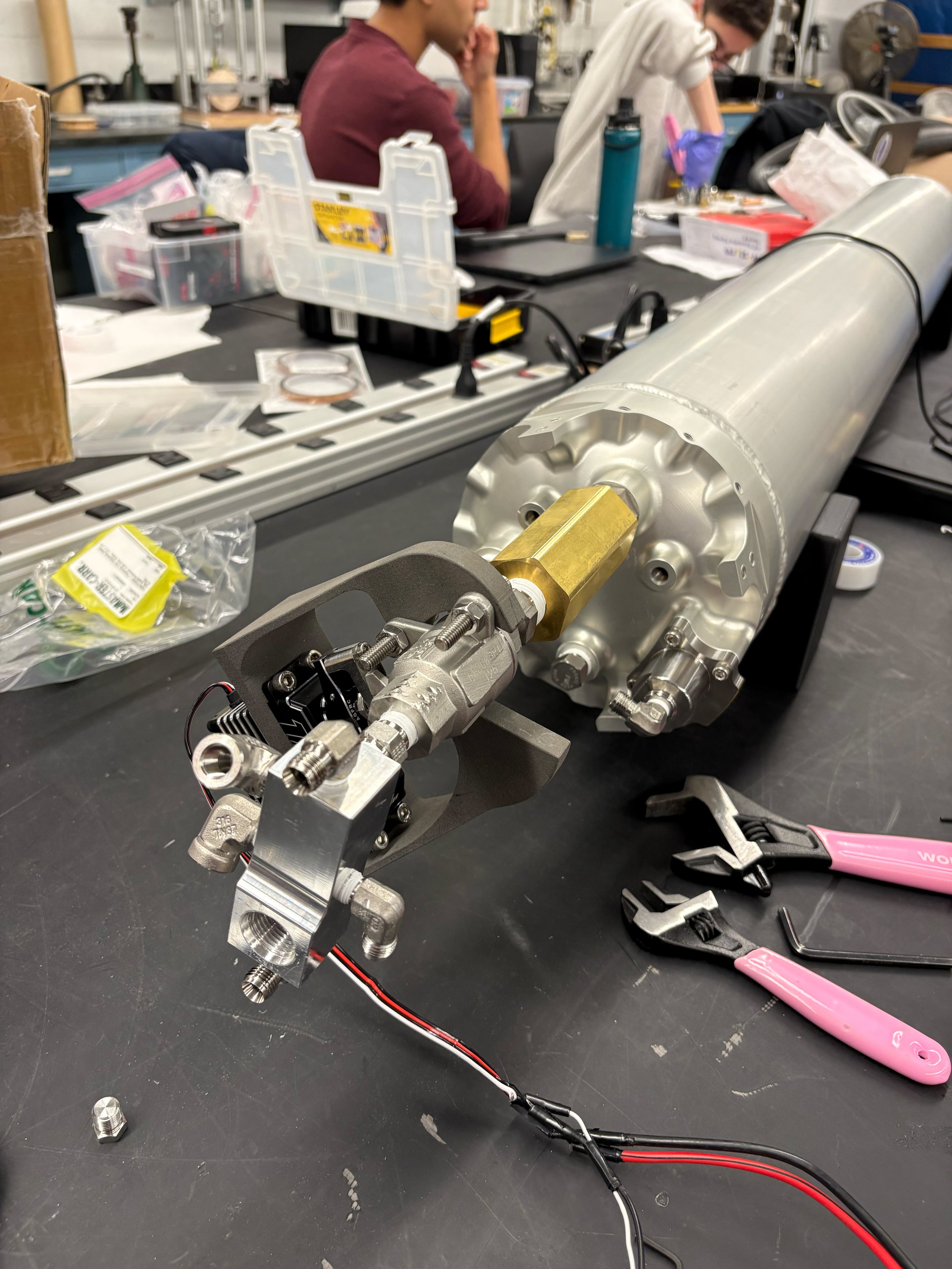
Second attempt at I-port installation

Testing setup with flight hardware
Integrated testing with electronics
Control loop:
The E-Reg utilizes an incremental/velocity-form PID with gain scheduling (dynamic gains). I chose to utilize a velocity-form PID to avoid integral windup issues. The incremental form also works cleanly with dynamic gains. As the PID output calculates a change in the valve angle rather than calculating an absolute valve angle, gain changes during operation lead to smaller changes to the controller output. A holding angle is carried over from the previous PID output rather than living in an integral term accumulation as it does in a regular PID. In a regular PID, multiplying changing gains with the absolute error can cause large step changes in the commanded angle, particularly when the integral term of the PID is scaled by a constantly changing Ki, arbitrarily moving around any existing hold angle.
Gain scheduling is based on COPV pressures. During an engine fire or cold flow, the COPV drains and the ullage volume increases rapidly, requiring constantly increasing flow to compensate for these effects and keep tank pressure constant. As COPV pressure drops, the PID gains scale and become more aggressive. The scaling factor was estimated with simulation, then adjusted over the course of several cold flows.
Simulation:
I developed this Simulink model of our fluid system, modeling a pressurized drain of our liquid oxygen tank with an E-Reg pressurizing the tank. My team lead at the time, Theo, developed a discrete tank pressurization and heat transfer physics model in Python. He used static fire data from the 2024-2025 rocket to adjust model parameters until the simulation’s outputs matched testing data. I modified his model to work as a plant in Simulink. Instead of solving for the CdA required to keep the ullage pressure at setpoint, I changed the simulation to take an area value as an input, run one timestep, then output system pressures to the loop where an incremental PID with dynamic gains outputs an angle. That angle is converted to a corresponding orifice area and plugged back into the Python simulation.

This is an example of a fairly well-tuned simulation. We observe oscillatory pressure for ~1.5s once the simulation starts draining LOX from the tank, then the tank pressure converges well onto the 450 psi setpoint.

System Pressures vs Time

Corresponding Regulator Cd*A (in2) vs Time
Sub-scale testing:
In the fall of 2025, I set up component-level testing to experimentally validate this design without relying on full-scale cold flow testing off-campus. The E-Reg is a high-risk component; there was a large concern that it may fail during system-level tests, and we’d have to switch back to a dome-loaded regulator, which would require a redesign of the GN2 system to fit a dome-loaded regulator and provide pilot pressure to the regulator.
I built a compressed air testing setup alongside our electronics team. The inlet side of the valve is connected to a low-pressure regulator, which is connected to shop air (~100-110 psi). The valve regulates pressure in a downstream volume pieced together with tubing and hardware from years prior. There is a needle valve connected to the downstream volume. The upstream pressure regulator’s setpoint can be lowered during a test as an analog to a decreasing COPV pressure, and the downstream needle valve can be gradually opened during a test as an analog to a growing ullage volume. An orifice was substituted in for the needle valve at times, as seen in the images below.
I was able to use this setup to rapidly test the E-Reg. I tried different control architectures such as fixed gains vs dynamic gains. I was also able to force the valve to move to a specific angle while the control loop was running to serve as a disturbance to the system; this allowed us to see how quickly the control loop could return to the setpoint and how large overshoots could be.
Here is an example of one test that was run:

Demonstrates the controller's ability to hold within ± 5 psi of a 50 psi setpoint
We introduced two disturbances, moving the servo to 20 and 60 degrees while the loop was running, and showed the controller’s ability to quickly recover
Heavy backlash is evident in this data from the square waveform of the pressure curve in the downstream pressure transducer. We can also see that we don’t observe pressure change until after ~10 degrees of actuator movement.
The backlash problem we saw in subscale testing was solved in two ways. First, we ensured that our stainless steel coupler had a tighter fit with the ball valve stem than the previous aluminum one did. In the code for our controller, we also had the servo move an additional 5 degrees any time the direction of travel changed, providing backlash compensation.


Early testing setup
Cold flow testing:
My teammates and I integrated the E-Reg into our fluids system and began a cold flow campaign in March of 2026.
The E-Reg’s functions were split into two modes, stage 1 and stage 2. Stage 1 caps the maximum servo angle at 19 degrees. This mode is intended for tank pressurization before our run valve opens. We only allow the valve to open slightly to slowly pressurize the ullage and prevent overpressurization. Stage 2 caps the max angle of the valve at 80 degrees, past the point it is fully open. Stage 2 kicks in immediately after the run valve is opened and LOX starts flowing out of the tank.

This is a cold flow on 3/27/26
We can see a slow pressurization at the start (stage 1). The ullage pressurizes, GN2 experiences ullage collapse, and the E-Reg compensates and re-pressurizes slightly.
In this test, once the LOX run valve opened (green), the LOX tank pressure tracked ~10-15 psi under setpoint for most of the test; however, we can see that the trace is fairly smooth, and we did not experience much oscillation in tank pressure.
At the ~2960s mark, COPV pressure drops below 500 psi, and the regulator can no longer supply enough GN2 to keep the tank at pressure.

This is a cold flow test on 5/1/26 that used more aggressive PID gains
We see very similar pressurization behavior during stage 1.
Once the run valve opens (green), we see oscillatory behavior with an amplitude of roughly 20 psi. The PID gains are too aggressive here, leading to hunting around the setpoint. As the ullage volume grows and COPV pressure drops, we see these oscillations weakening, which makes sense as ullage volume growth and upstream pressure drop sort of act as an increasing damping term in an oscillator.

Cold flow testing
Static fire:
After a successful cold flow campaign and a few unsuccessful static fire attempts, we had a good static fire in mid-May where the E-Reg performed nominally!

Static fire on 5/13/26
Nominal tank pressurization prior to LOX run valve opening.
There was a dip in LOX tank pressure to roughly 380 psi right after the run valve opened, a startup transient that still needs to be addressed.
However, the E-Reg recovered quickly and maintained tank pressure to within ± 10 psi of the 450 psi setpoint pressure until our COPV pressure hit ~550 psi and we did not have enough GN2 to pressurize to 450 psi anymore (E-Reg was fully open by this point).
