Environmental Control Chamber
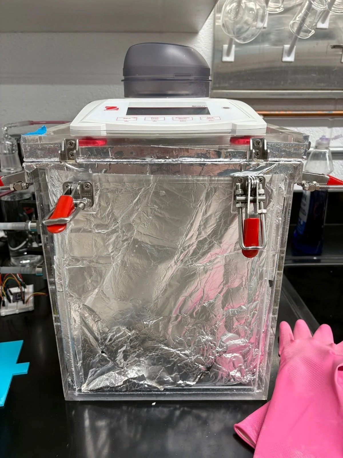
I work at the Nordness group at Columbia, an Earth and Environmental Engineering lab, where I started working in the summer of 2025. I was tasked with automating humidity and temperature control in the environmental control chamber shown below. The chamber is used for atmospheric water harvesting research where we characterize the absorption and desorption performance of novel hygroscopic materials across different temperature and humidity ranges. The previous setup used a hot plate at the bottom of the box to heat the box up; this method was slow, and controlling the temperature was very difficult. For humidity control, a pressure regulator was installed on the central compressed-air supply to reduce line pressure to 1 bar. Downstream of the regulator, a primary needle valve provides overall flow control before the line splits into two branches: one routed through a bubbler to generate humid air, and the other through a desiccant dryer to supply dry air. Each branch has a secondary needle valve for fine flow regulation prior to entering the environmental chamber. Controlling the humidity in an analog manner was difficult and required constant watching and tuning.
Experimental Chamber
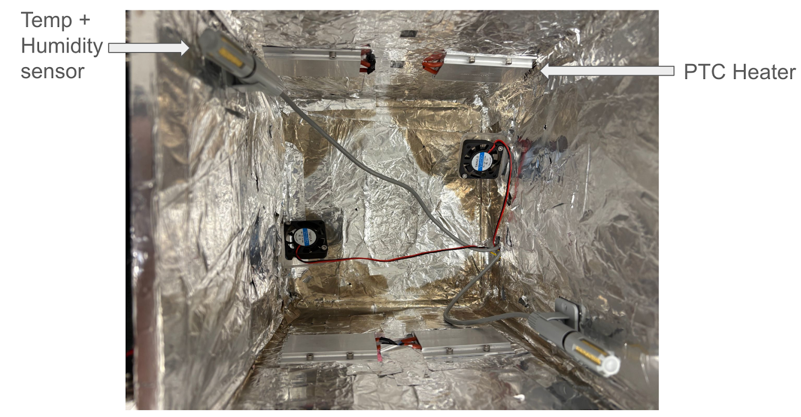
I used an Arduino Nano for this project. For temperature and humidity sensing, I utilized two AM2315C temperature and humidity probes mounted in opposing corners in the box; as samples were hung about two inches below the top of the box, the temperature and humidity conditions near the top of the box were the most relevant for experiments, so I elected not to mount extra sensors near the bottom of the box.
Temperature control:
I mounted four 110°C PTC (positive temperature coefficient) heaters on opposing walls of the box and connected them in parallel to a solid-state relay, which was connected to a wall outlet. From initial testing, I found that it took too long for the box to heat up, and there was a temperature difference of up to 6°C in opposing corners of the setup. To promote greater convection and fix the temperature gradient problem, I mounted two 40mm fans with custom laser-cut acrylic mounts near the bottom of the box.
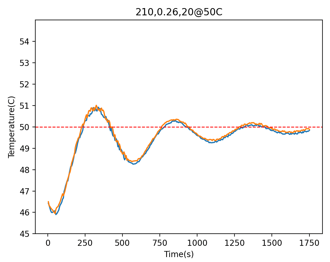
PTC heaters operate in a binary way, so for the control logic, I utilized a time-proportional control scheme. A cycle time of 10s was chosen, and the Arduino computed a PID output that corresponded to how long within each cycle time the heaters should be switched on. Additionally, I used dynamic gains, with different sets of gains for the temperature ranges of [30°C,40°C], (45°C, 55°C], and (55°C, 65°C]. After tuning, the controller could reach a steady state to within half a degree for the range of 30 °C to 65 °C.
Inside the chamber
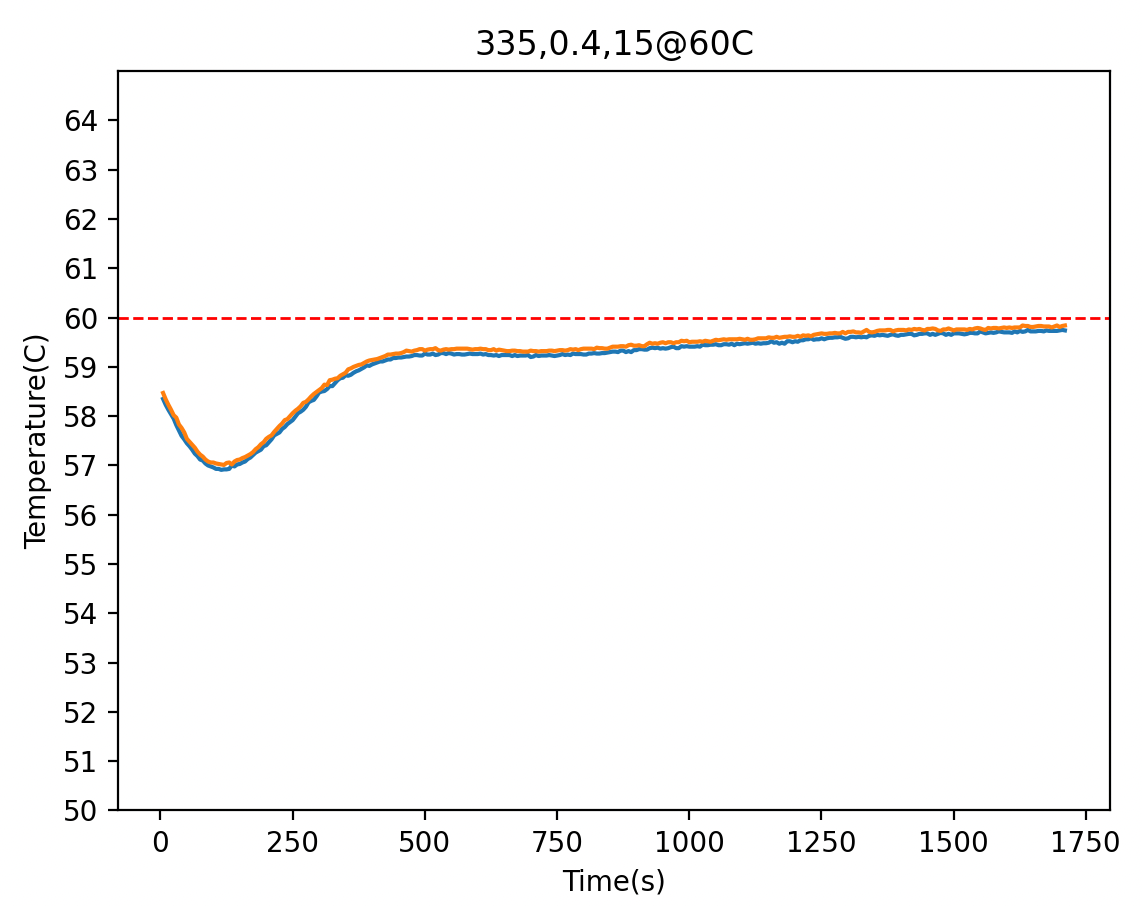
Here are two graphs showing the performance of the controller at 50°C and 60°C:
Humidity control:
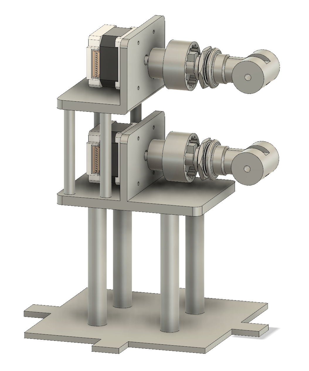
I utilized two stepper motors to control each of the humid and dry air lines. I designed a stand for the motors and an adapter for the shaft to the valve handle in CAD and 3D printed them. I drove the motors at .8A each with A4988 drivers, and microstepped the motors to 3200 steps/revolution. The microstepping gave the advantage of significantly quieter operation alongside the increased resolution (although 3200 steps/revolution was much more than necessary).
For the control logic, I programmed the PID output to correspond to incremental step changes with a max step increment of 50 every 200ms, which helped ensure that there was no ‘jerky’ motion in the motors. Initially, I tried to have the PID move both valves synchronously, but found that all I really needed was for the PID output to control how open the humid air line is. For the dry air line, I programmed the motor to move to a fixed position dependent on the humidity setpoint. For lower humidity setpoints (30-40% relative humidity), I opened the dry air line half a revolution and kept it there. For higher humidity setpoints, I had the motors open the line to a quarter of a turn. Having a fixed amount of dry air going in with a variable amount of humid air was more than enough to achieve good steady states.

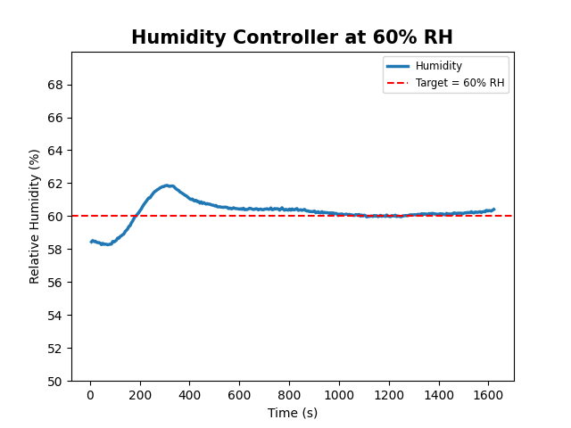
Here is a graph of the humidity controller maintaining a 60% relative humidity in the chamber:
Electronics:
Here is a list of all major electronics components and sensors used:
Arduino Nano
AM2315C temperature + humidity sensor
1.5A NEMA17 Stepper Motors (I drove them at .8A each)
A4988 Stepper motor driver
TCA9548A Multiplexer
SSD1306 OLED Display
DC to AC Solid State Relay
I prototyped everything on breadboards and am in the process of moving everything over to a perforated circuit board for a more permanent setup. I used the OLED screen to output current humidity and temperature values.
Here is the electronics schematic of the whole setup:

Picture of the current setup:
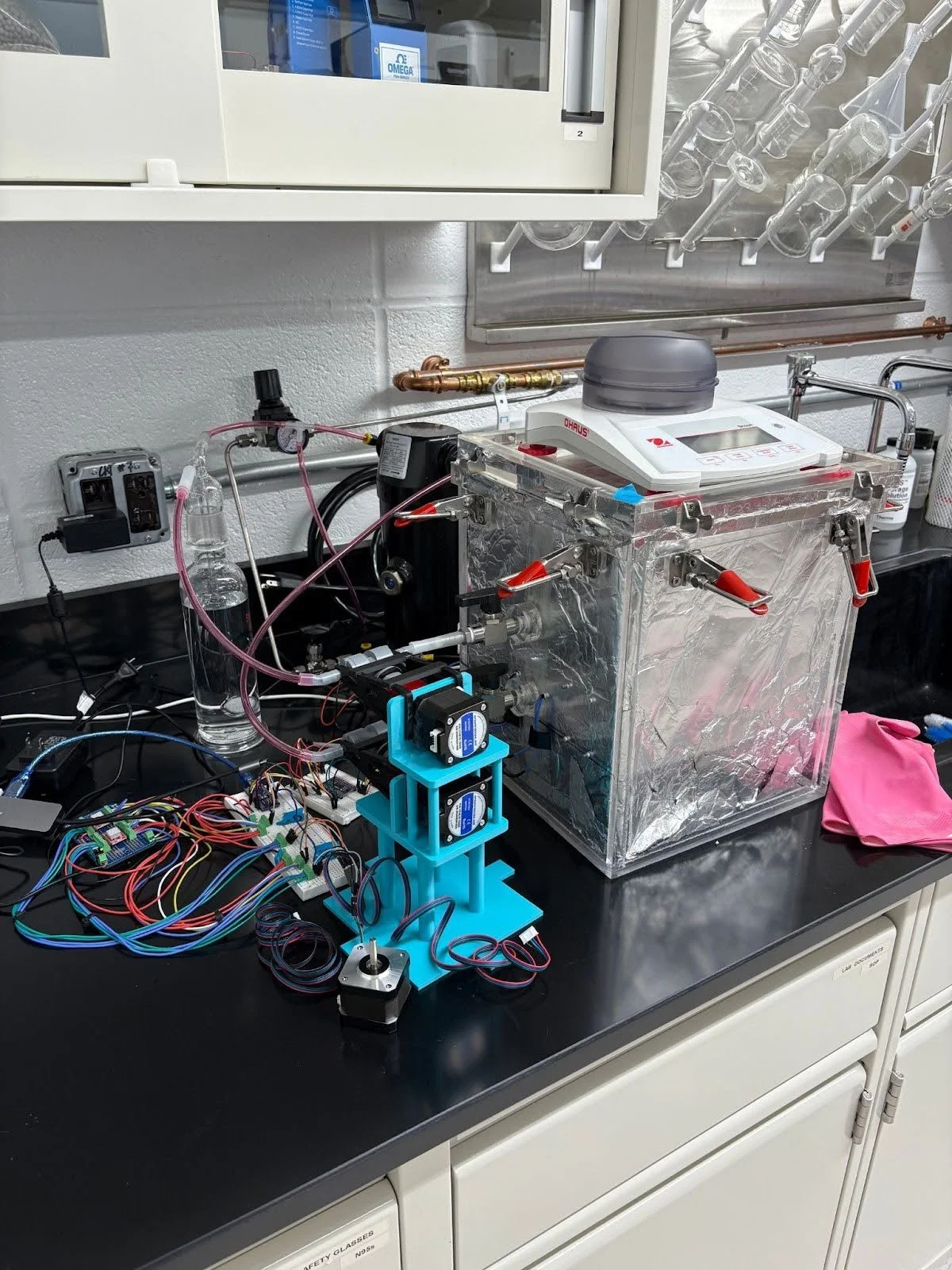
I’m still finishing this project up. Everything works, but as you can tell from the picture, it’s very messy. I need to finish moving everything over to a perfboard, and cable management is currently nonexistent. There are also a few functionalities I’m still working to implement:
Better user interface and data collection. Currently, the code has to be reuploaded to the Arduino every time the setpoint changes. I’m working on making a simple physical user interface with buttons so that the setpoints can be changed without touching the code. The temperature and humidity data over time are collected through the serial-port terminal application CoolTerm and manually saved as CSV files. I’m going to automate this process.
Moving to a cleaner PCB implementation, I’m designing the PCBs in KiCad currently and plan on moving everything over to a custom PCB.
Presentation:
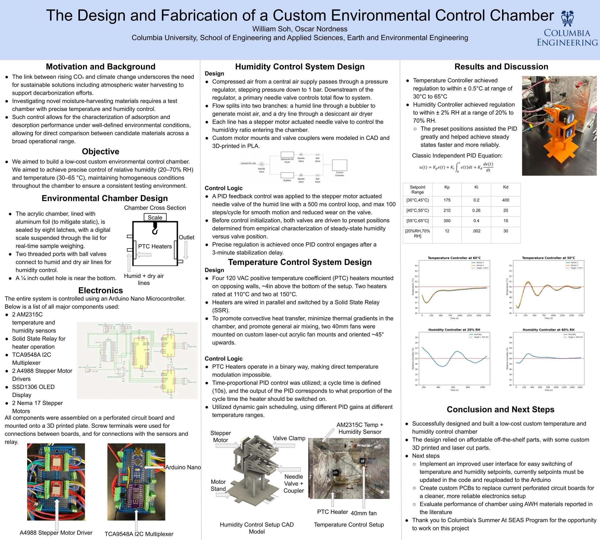
I presented this project at the American Institute of Chemical Engineers(AIChE) 2025 Student Conference’s undergraduate poster competition. There, I won 1st place in the Environmental 2 group (they split each category into groups), and 3rd place overall in the Environmental category. Here is the poster I presented!