Pinball Machine
In my first semester at Columbia, I took an introductory engineering course titled Art of Engineering. Our final project was a semester-long engineering project where in teams of 4-5, we had to create some kind of physical game. We were given a 50-dollar budget and a basic Arduino starter kit and let loose for the semester. We decided to build a pinball machine. We modeled our frame in CAD and got to work on making all the parts for the machine.
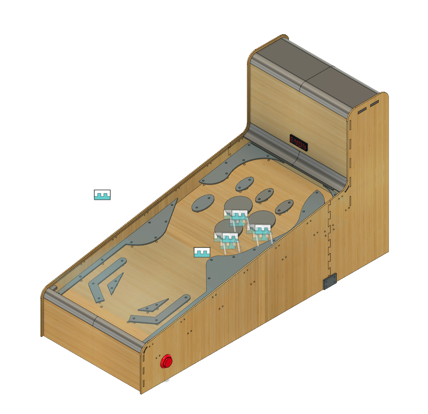
I designed the flipper mechanism that would hit the ball. Utilizing two push-pull solenoids, I modeled and 3D printed linkages that would turn the linear motion of the push-pull solenoid into the rotational motion necessary for the flipper. My teammate designed a pop-bumper like the ones they have in real arcade pinball. We decided to let the user control the pop-bumpers with the same buttons as the flippers; the left flipper and two bumpers on the left were controlled by the left side button; the right flipper and the one bumper on the right were controlled by the right side button.
Flipper mechanism:

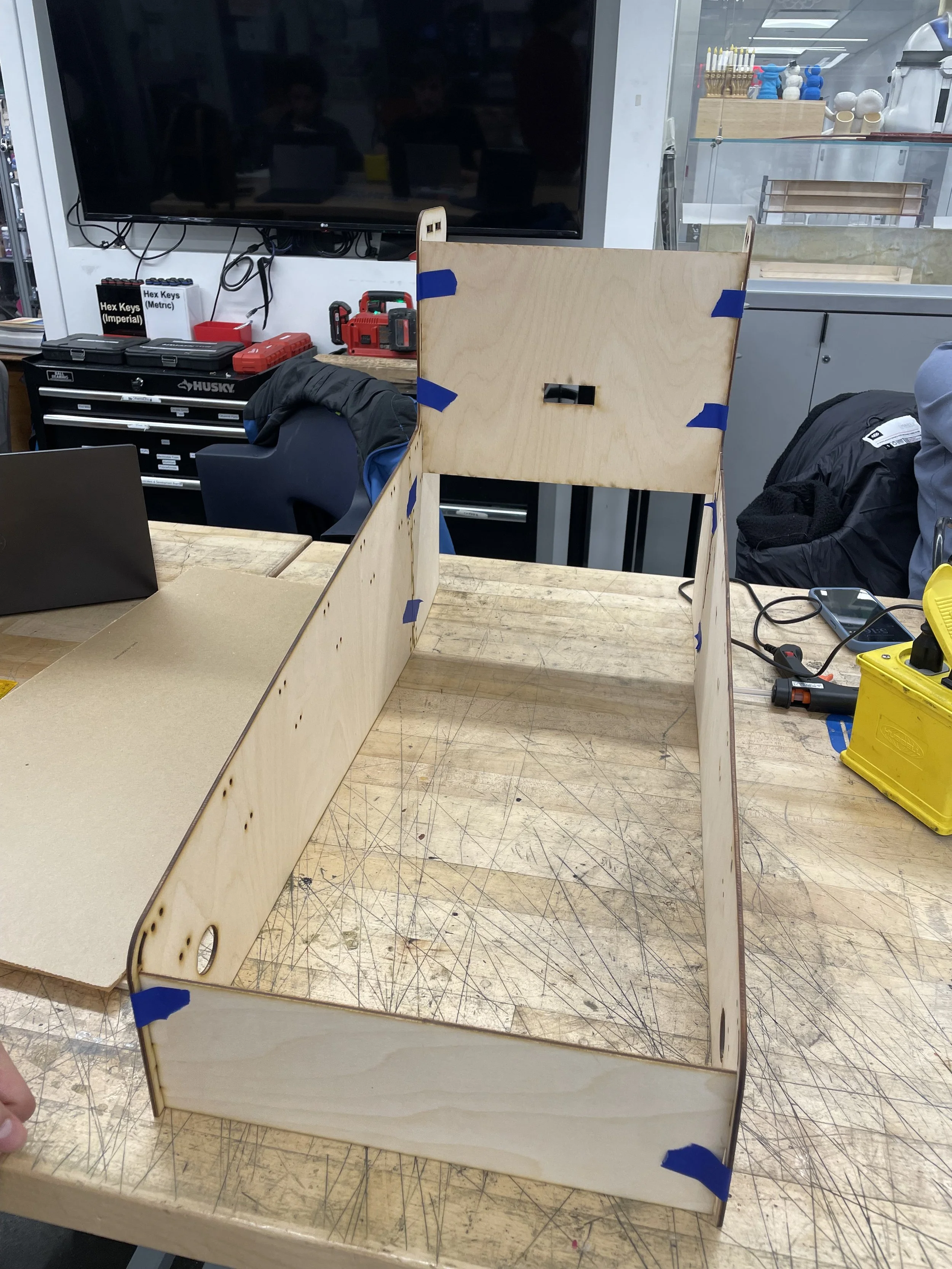
We laser-cut the frame and the obstacles/boundaries for the game board out of wood, and 3D printed parts such as the plunger (the plunger and spring for the plunger were epoxied in). For electronics, we utilized a laser and a laser sensor for ball detection. When the ball passed certain laser ‘gates’, the player gained points, which they could see on the display. When the ball passed the laser ‘gate’ behind the flippers, the game ended. Everything was controlled by an Arduino Uno. For controlling the push-pull solenoid, we followed a circuit diagram found online and soldered all components on a perfboard.
Here is our final product:
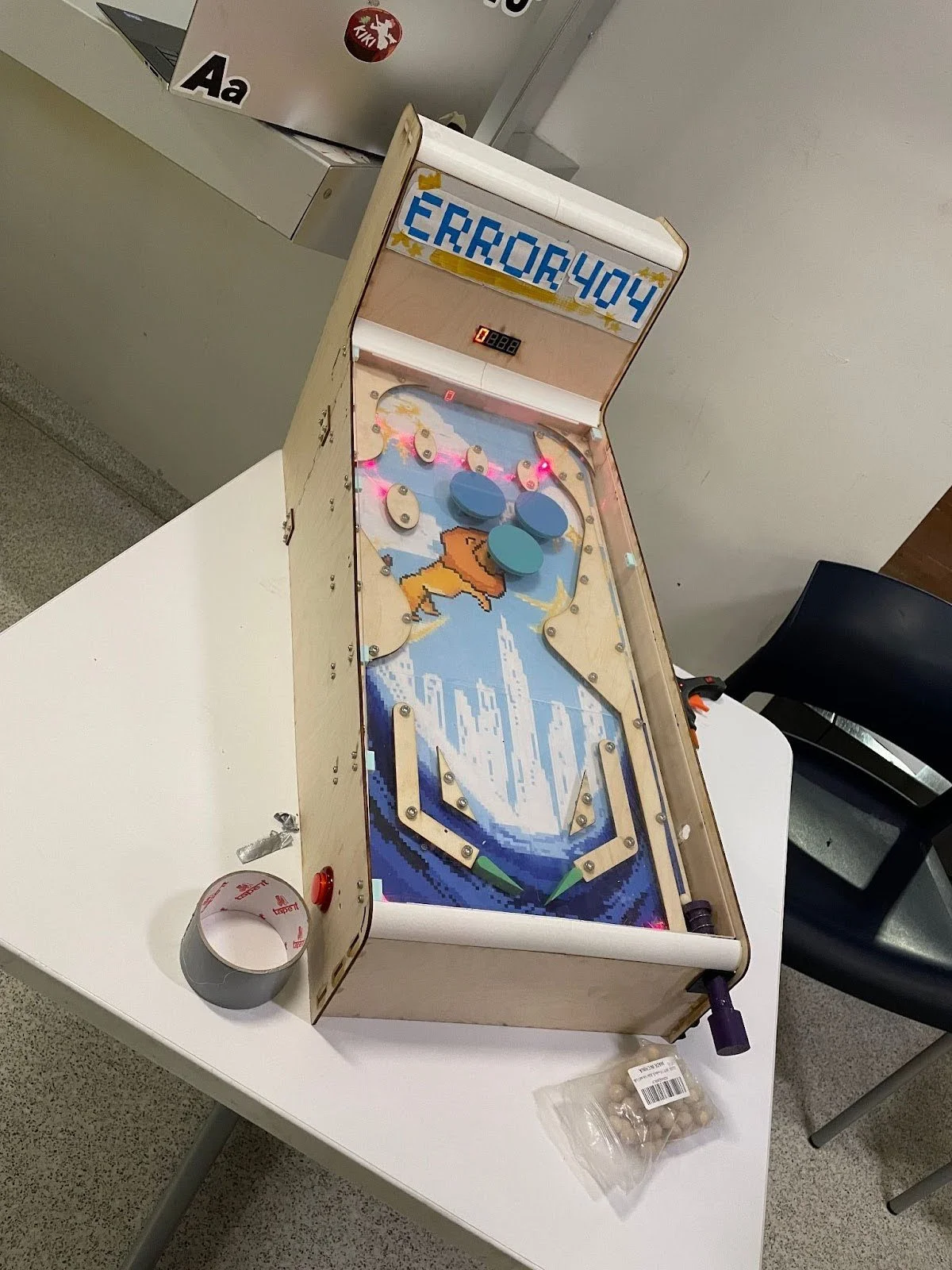
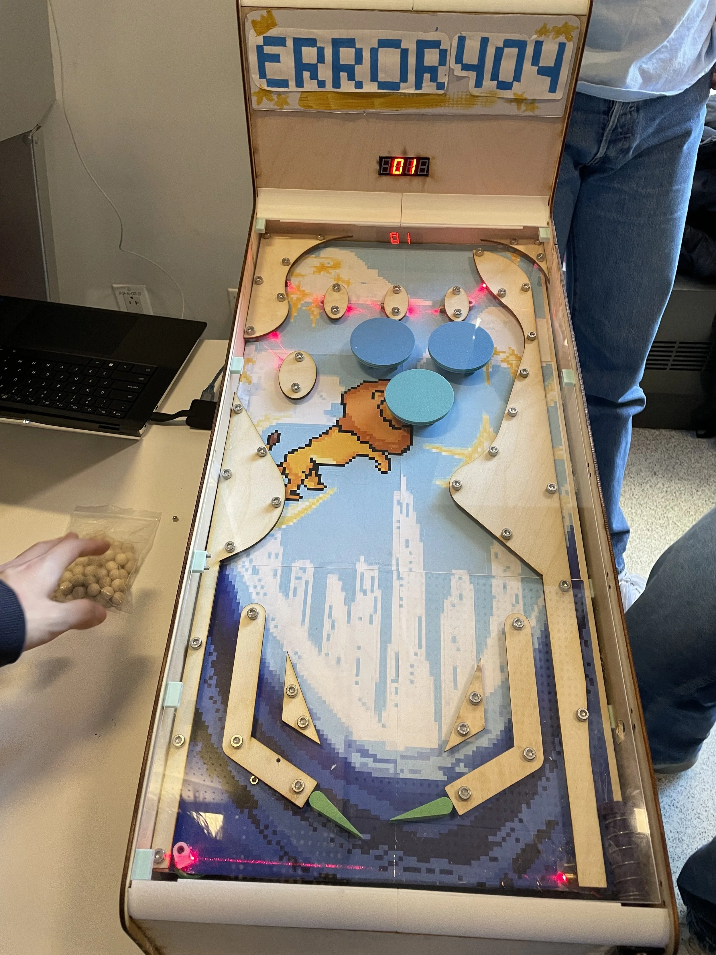
I wish I had taken more pictures of our build and design process. Either way, this was a seriously fun project and I had a great time working on it with friends. Showing our pinball machine at our class’s project expo was an awesome way to cap off my first semester of college!